


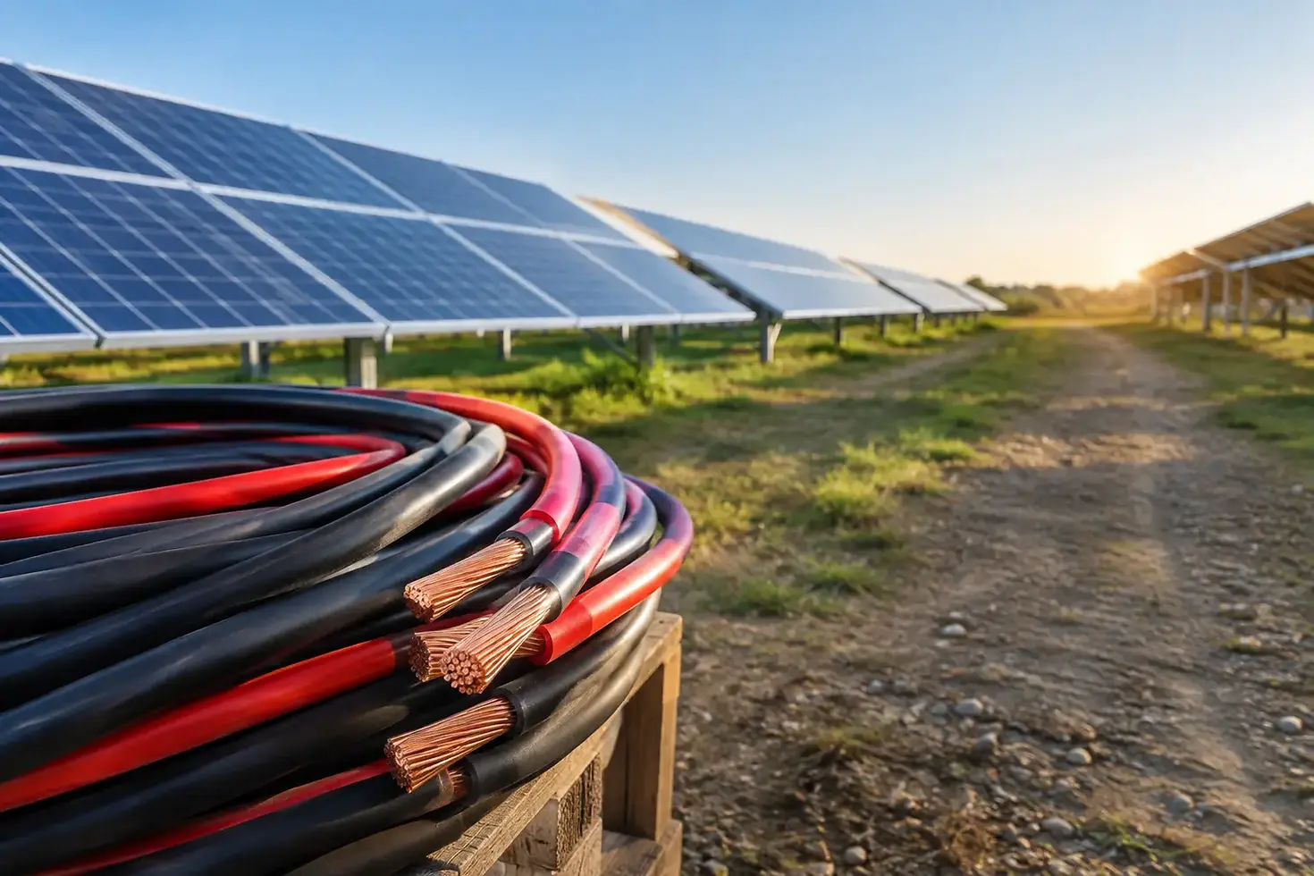
Solar Farm Cable Deployment for Reliable Output

A solar project can have high-efficiency modules, properly sized inverters, and a strong civil design, yet still lose performance through poor solar farm cable deployment. Cable routes, conductor selection, voltage-drop control, termination quality, and field installation practices all affect whether generated power reaches the point of interconnection reliably. For EPC contractors, developers, and procurement teams, cable planning should begin well before construction crews arrive on site.
The objective is not simply to install enough cable to connect every string and inverter. The objective is to build a collection system that performs under heat, UV exposure, moisture, mechanical stress, and decades of operating cycles while remaining practical to install, inspect, and maintain.
Why Solar Farm Cable Deployment Needs Early Planning
Cable decisions made late in the engineering process often create expensive field changes. A route that looks efficient on a layout drawing may cross drainage channels, access roads, rocky ground, tracker foundations, or areas with difficult excavation conditions. Changes at that stage can increase trenching quantities, require additional joints, or delay energization.
Early cable planning aligns electrical design with the actual site. It establishes where DC string circuits will run, how inverter stations will collect AC output, where medium-voltage feeders will be placed, and how communications and grounding conductors will be protected. The final approach depends on plant capacity, block size, terrain, soil conditions, equipment arrangement, local code requirements, and the project owner’s maintenance strategy.
A utility-scale site may use long underground collector runs between inverter stations and a substation. A commercial ground-mount project may have shorter, more concentrated routes. In both cases, the cable system must be treated as an engineered asset rather than a basic installation material.
Cable Selection Starts With the Electrical Design
Correct cable selection begins with operating voltage, current-carrying capacity, installation method, and environmental exposure. DC circuits from photovoltaic strings require solar-rated conductors designed for outdoor conditions. These cables must tolerate direct sunlight, temperature variation, and the electrical characteristics of DC systems. AC low-voltage power cables connect combiner equipment, inverters, and auxiliary systems, while medium-voltage cables carry collected energy toward the transformer and grid connection.
Conductor material is an important commercial and technical decision. Copper offers high conductivity and can support compact cable designs, which may be useful where space is restricted or termination requirements are demanding. Aluminum can provide a cost-effective option for larger feeder sizes when the cable design, connector compatibility, and installation practices are properly managed. Neither choice is automatically better. The right option depends on ampacity, route length, installation environment, project budget, and available connection hardware.
Insulation and sheath materials also need attention. Cables exposed above ground require strong resistance to UV radiation and weathering. Buried cables require suitable mechanical protection and moisture resistance. Where cables are installed in ducts, trays, or direct-buried trenches, thermal conditions can differ significantly. A cable that meets current requirements in open air may need derating when installed in a congested duct bank or grouped with other circuits.
Voltage Drop Is a Design Issue, Not a Field Adjustment
Voltage drop can reduce plant efficiency and should be evaluated across both DC and AC portions of the system. Long string runs, undersized conductors, elevated conductor temperatures, and heavily loaded collection circuits can all increase losses. Selecting a larger conductor cross-section may raise initial material cost, but it can reduce lifetime energy losses and improve the project’s financial performance.
The appropriate balance is project-specific. Designers should compare cable cost, installation cost, anticipated generation, and long-term loss value rather than selecting cable size only by minimum ampacity.
Designing Practical Cable Routes
The best route is not always the shortest route. A direct line may pass through locations that create construction risk or restrict future access. Cable routes should avoid unnecessary crossings, areas subject to standing water, high-traffic vehicle paths, and locations where future civil work is likely. When crossings cannot be avoided, additional protection such as ducting, concrete encasement, warning tape, marker posts, or mechanical covers may be necessary according to the project specification and applicable standards.
Trench depth and separation requirements must be confirmed before excavation starts. Separation between power circuits, control cables, and fiber-optic cables helps limit interference, simplifies identification, and reduces the risk that one repair operation damages multiple systems. Fiber cables used for monitoring, SCADA, security, weather stations, and inverter communication deserve the same route discipline as power circuits. A communications fault can limit visibility into plant performance even when generation equipment remains operational.
Route plans should also identify pull locations, cable drum access, joint bays, and termination points. Large power cable drums require suitable delivery access and handling equipment. If a site has narrow roads, steep grades, or seasonal ground restrictions, logistics may influence the preferred cable lengths and drum sizes.
Installation Quality Controls Long-Term Performance
Many cable failures originate in installation, not manufacturing. Excessive pulling tension, inadequate bending radius, damaged insulation, poorly prepared terminations, and uncontrolled backfill can create faults that appear months or years after commissioning.
Before pulling begins, installation teams should verify cable drum identification, lengths, inspection condition, route readiness, and pulling calculations. Cable ends must be sealed against moisture entry during storage and installation. Where pulling equipment is used, the pulling force must remain within the cable manufacturer’s limits. Rollers, guides, and approved lubricants can reduce sheath damage, especially on long duct pulls.
For direct-buried installations, trench bottoms should be prepared to prevent sharp rocks or debris from contacting the cable sheath. Suitable bedding and selected backfill protect the cable and make compaction more consistent. The exact materials and depth requirements should follow the project specification, local regulations, and site soil conditions.
Terminations and Joints Require Equal Attention
A correctly selected cable can still fail at a poor connection. Terminations, lugs, glands, joints, and connector interfaces must match the conductor material, conductor size, insulation system, voltage class, and equipment connection point. Aluminum conductors in particular require correct preparation and compatible connectors to manage oxide formation and maintain a stable connection.
Workmanship controls should include calibrated torque tools, approved stripping dimensions, clean contact surfaces, phase identification, and documented inspection. On large sites, repeatable termination procedures are essential because hundreds or thousands of identical connections may be installed across multiple work crews.
Testing and Documentation Before Energization
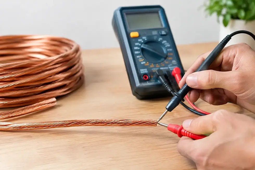
Testing should verify cable condition before the system is placed into service. Depending on the cable type and project requirements, this may include continuity testing, insulation resistance testing, sheath integrity testing, phasing checks, and voltage testing. Test values should be recorded by circuit and compared against approved acceptance criteria.
Documentation is equally valuable. Accurate as-built drawings should show routes, depths, cable types, joint locations, spare ducts, and termination points. Cable schedules should identify conductor size, voltage rating, circuit designation, drum number, and installed length. These records reduce troubleshooting time when maintenance is needed years later.
Thermal imaging after energization can help identify loose or high-resistance terminations. Regular inspection of exposed cable routes, tray sections, and equipment entry points can detect UV damage, rodent activity, mechanical impact, or water ingress before an outage occurs.
Procurement Factors That Affect Deployment
Cable supply must match the construction sequence. A technically suitable product delivered after trenching crews have completed their work can disrupt the entire project schedule. Procurement teams should confirm manufacturing lead times, drum lengths, packing requirements, test documentation, labeling, and export logistics early in the purchasing process.
For international projects, consistency in technical documentation matters as much as production capacity. Buyers should confirm applicable standards, conductor class, insulation and sheath construction, voltage rating, color identification, and required test reports before production. Custom cable lengths can reduce field joints and material waste, but they must be balanced against shipping limits, drum handling capability, and route pulling conditions.
ECI Wires supports industrial and energy projects with low-voltage power cable production, custom technical configurations, and export-ready supply coordination. For solar applications, clear specifications and early production planning help ensure that cable supply supports the installation program rather than becoming a critical-path risk.
Build the Cable System for the Operating Life of the Plant
Solar farms are designed to generate for decades. The cable system should be selected and installed with that operating life in mind, not only to pass commissioning. A disciplined approach to routing, cable sizing, environmental protection, installation controls, testing, and documentation gives owners a stronger foundation for reliable output and manageable maintenance long after the construction team leaves the site.


Comments